Upgrading your Creality K1 or K1 Max with a graphite plate offers superior flatness, faster heat transfer, and excellent adhesion for high-temperature materials like ABS and polycarbonate. Unlike traditional glass or magnetic beds, graphite's unique thermal properties ensure consistent first layers across the entire build surface. This guide provides step-by-step instructions for safely removing the stock flexible platform, installing the graphite plate, and recalibrating your Z-offset to accommodate the new surface thickness. Proper surface preparation and bed mesh recalibration are essential for optimal results.
Graphite Bed Build Plate For K1 Series
TABLE OF CONTENTS
More Information (Discord) : https://discord.com/channels/1154500511777693819/1362745993614987304 (https://discord.gg/yqcckKwjSK)
K1 Series (K1 / K1C / K1SE): (AU: 220 - 240V):
For older kits that magnet did not comes assembled, newer kits have magnet/heater pre-installed.
If you wipe the graphite plate with alcohol or any liquid make sure that it is completely dry before gluing the heater and magnet!!! Graphite has pores and liquid will be trapped inside it and will make the glue bubble when heated.
I suggest gluing the magnet on a 100C hot bed (the last step of installation) to make sure the graphite is dry and it glues flat. This was tested couple time and worked great.
You can follow the stock replacement guide for the bed, but following below for wiring guide. Newer kits are shipping with after market SSR, you wish to use that, please print the SSR mount and follow wiring for after market mounting option.
Before installing I suggest printing the SSR mount that you can install on the rib right next to the motherboard:
"https://www.printables.com/model/1182750-k1-k1c-k1se-ssr-mount-for-bed-heater-upgrade"
And bed leveling knobs for M4 screws:
"https://www.printables.com/model/1182770-bed-leveling-knob-for-m4-screw-m4-nut"
The 500W AC heater has inbuilt 150C self-recovery overheat protection switch for safety.
It has 5 wires:
2 red wires = thermistor
2 white and 1 yellow wires to connect to either 220v or 110v:
220v: ignore the yellow wire and connect white wires only
110v: connect 2 white wire together to one terminal and the yellow wire to the other.
If you are using the stock bed probe, you need to keep the cable that connects the bed leveling MCU to the mainboard in order for the stock bed probe to work.
Remove this cable from the stock bed wiring and use it to connect the bed MCU to the mainboard.

Wiring Guide:
- Ground Wiring (Wiring, require re-crimp one end to RV1.25-4) Use the one of back 2 build plate alignment to secure ground wiring with lock washer, you may need source slight longer fasteners if you're using lock washer. The Ground can wire to the power supply shared GND.
Software:
Thermistor type is NTC 3950 100K. in "printer.cfg" change the sensor_type to sensor_type: NTC 100K MGB18-104F39050L32 and do the pid calibration in the console: PID_CALIBRATE HEATER=heater_bed TARGET=100
K1 Max (K1 Max): (AU: 220 - 240V):
Older Information: (Where assembly was part assembly, you can ignore if you're installing new assembly)
If you wipe the graphite plate with alcohol or any liquid make sure that it is completely dry before gluing the heater and magnet!!! Graphite has pores and liquid will be trapped inside it and will make the glue bubble when heated.
I suggest gluing the magnet on a 100C hot bed (the last step of installation) to make sure the graphite is dry and it glues flat. This was tested couple time and worked great.
Before installing I suggest printing bed leveling knobs for M4 screws:
"https://www.printables.com/model/1182770-bed-leveling-knob-for-m4-screw-m4-nut"
General Notes:
The 1000W AC heater has inbuilt 150C self-recovery overheat protection switch for safety.
It has 5 wires:
2 red wires = thermistor
2 white and 1 yellow wires to connect to either 220v or 110v:
220v: ignore the yellow wire and connect white wires only
110v: connect 2 white wire together to one terminal and the yellow wire to the other.
Note: For K1 Max: Attach the grounding wire using the M3*6 flat-headed bolt from the bottom of the plate, it will be hidden under the heater. For K1: after installation ground one of the build plate alignment bolts or one of the mounting bolts (under the bed tray. there is pictures below).
Newer Kits will include a SSR from R3men, its up to if you want to install it or use stock SSR, just follow below steps depending if you're using stock
230V Connection (Stock SSR):
Wiring Guide:
- Ground Wiring (Re-Use Stock Ground Wiring) Use the one of back 2 build plate alignment to secure ground wiring with lock washer, you may need source slight longer fasteners if you're using lock washer.
1. Connect 2 white wires to COM and 220B slots on SSR. Connect the yellow and green grounding wire (grounding wire has a ring terminal).
2. Isolate with tape and DO NOT connect the 110v yellow wire.
3. Connect thermistor to the mainboard.

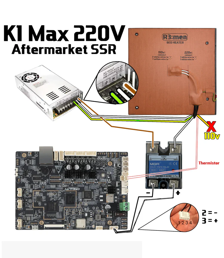
230V Connection (Aftermarket SSR):
Download an SSR mount using this link.
Thank you KrzysztofGW for designing it!
1. Connect 1 white wire to OUTPUT 2 port on SSR. The other white wire to PSU N. Connect the yellow and green grounding wire to PSU grounding port. Connect the stock wire that comes from PSU L to OUTPUT 1 port on SSR.Isolate with tape and DO NOT connect the 110v yellow wire.
3. There is a 4-wire cable that connects the board with stock SSR. Connect 2 middle wires from this cable to the SSR control side. Normally the second wire is - and the third is +, but it can be the other way around.
4. Connect thermistor to the mainboard.

Bed Mounting Options:
Rigid bed mounts
If you use stock bed probe (PRTouch) then use metal standoffs with M4 bolts.

Springs and knobs
If you use cartographer or other Eddy sensor bed probes, then you may use springs with M4 bolts with bed knobs for easy bed leveling using screw tilt adjust. You may buy the bed knobs or print the knobs from Printables.

Software:
Thermistor type is NTC 3950 100K. in "printer.cfg" change the sensor_type to sensor_type: NTC 100K MGB18-104F39050L32 and do the pid calibration in the console: PID_CALIBRATE HEATER=heater_bed TARGET=100
Newer Board may be using newer thermistor "sensor_type: NTC 100K MGB18-104F39050L32 "
On 120V, you may want to set max_power to 0.8 to reduce the load on your UPS and electrical switches.


Temperature Error
If you see negative temperature readings and printer throws temperature errors, that means that you did not change the thermistor type in the config file. See the previous step.
Also, some buyers had issues with the stock SSR. Our heater is more powerful than the stock heater (~1100W) and the stock SSR may not cope with it. If you see that bed heater power is 100% but the bed temperature is not changing, then you need to swap the stock SSR with an aftermarket one.

Was this article helpful?
That’s Great!
Thank you for your feedback
Sorry! We couldn't be helpful
Thank you for your feedback
Feedback sent
We appreciate your effort and will try to fix the article