Created by DREMC STORE, Modified on Sat, 22 Aug at 12:10 PM by DREMC STORE
This guide will walk you through the process of replacing the X/Y belts on your Anycubic Kobra S1, S1 Combo, or S1 Max 3D printer.
Over time, belts can stretch or wear, leading to print issues like layer shifts and poor surface quality. Replacing them is a key maintenance task that will restore your printer's precision.
Replace Both Belts: If one belt is worn, it's a good idea to replace both the X and Y belts simultaneously to ensure even performance. If you're getting them in single longer length, ensure both belts are cut to same length, you can always trim away longer length so where possible we recommended cut them longer than spec or leave them uncut and trim once installed and tensioned where possible.
Use Genuine Parts: For the best fit and reliability, use OEM Anycubic belt replacement kits or higher quality branded timing belts such as Gates.
1.5metres 2GT 6mm per axis (2 axis per printer, A/B or X/Y) For Core XY. You can purchased a longer length and trim down to size, most 3d printer supplier should have plenty of those belts available.
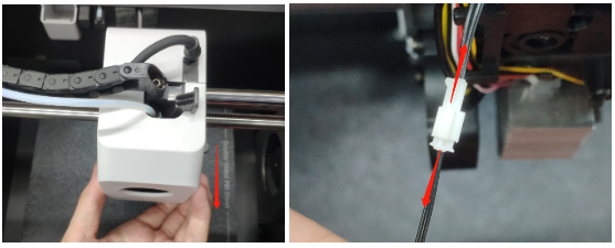
1. Remove the front shell of the print head and remove the fan plug.
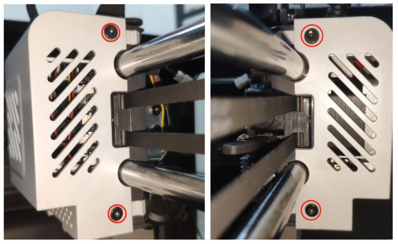
2. Use the S2.0 Allen Key to unscrew the fixing screws of the rear shell of the print head.
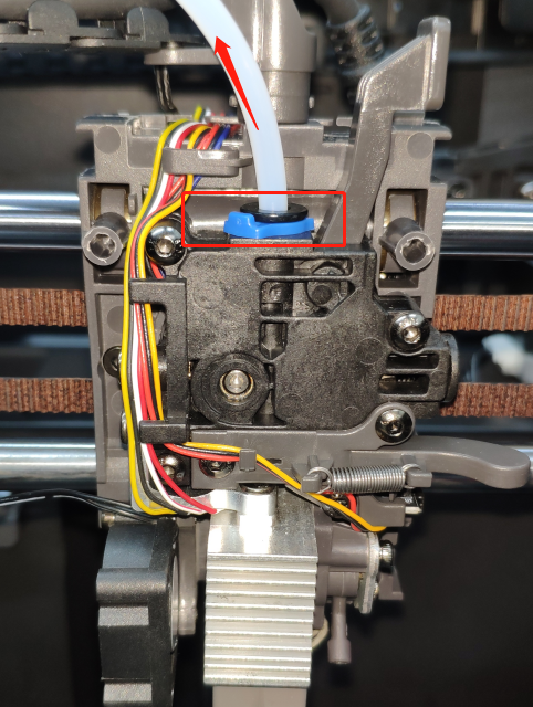
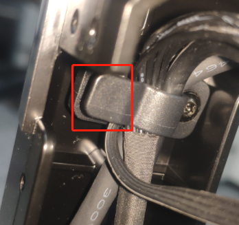
3. Remove the blue buckle, press the black press head and remove the feed tube upward.
Step 3: Disassemble the extruder and print head
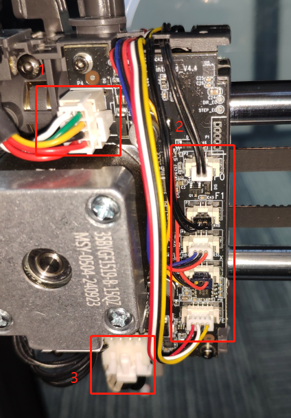
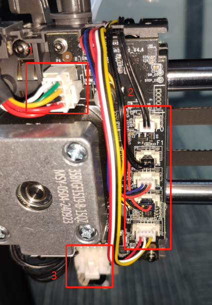
1. Remove the wire harness of the material break detection board, the wire harness plug of the cutter detection board, the wire harness plug of the print head, and the wire harness plug of the hot end of the print head.
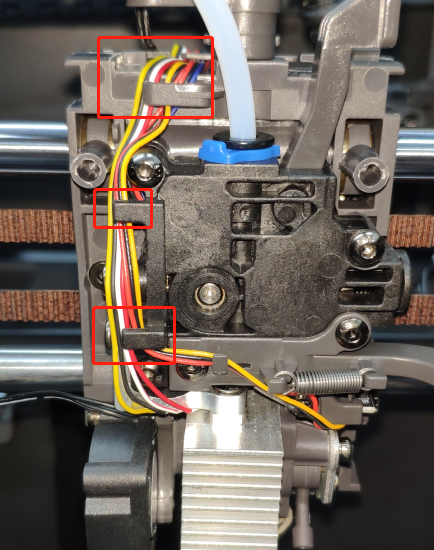
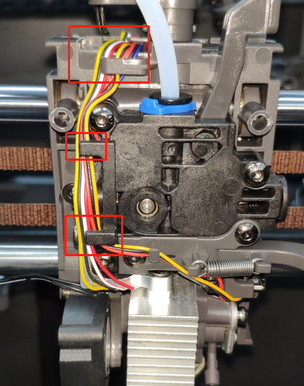
2. Remove the wire harness stuck in the extruder from the buckle.
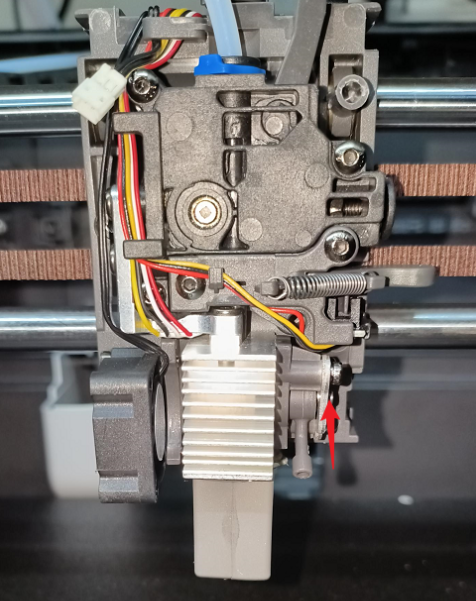
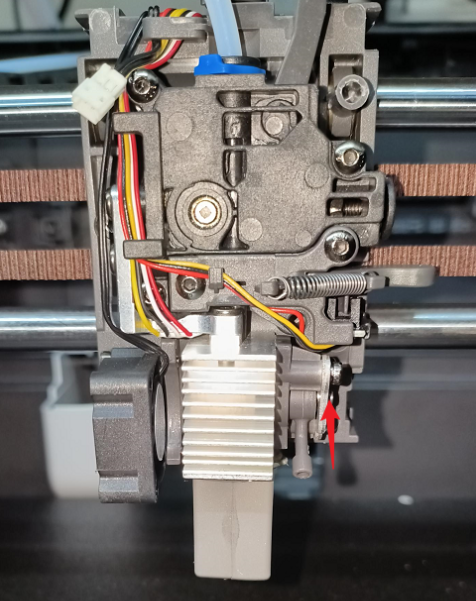
3. Pull the buckle that fixes the quick-release hot end upward, unplug the quick-release hot end connection, and then remove the quick-release hot end.
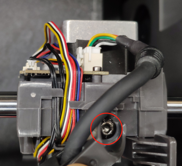
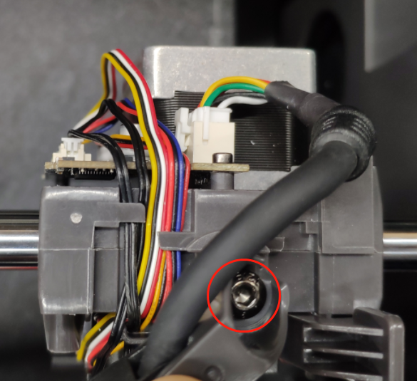
4. Use an S2.5 Allen Key to unscrew the drag chain fixing screws.
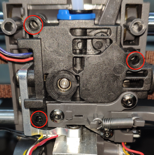
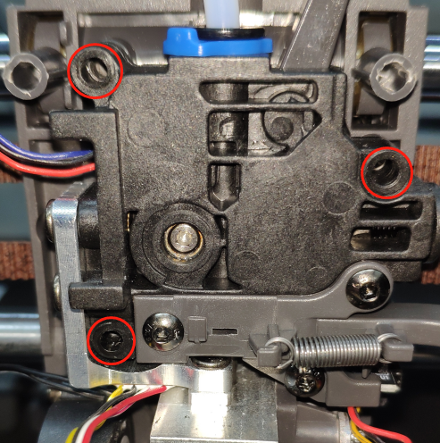
5. Use an S2.0 Allen Key to unscrew the extruder module fixing screws and remove the extruder module.
Step 4: Disassemble the top frame
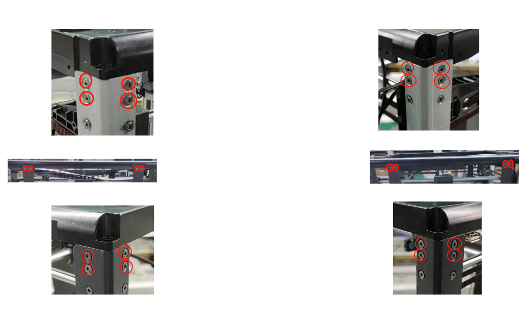
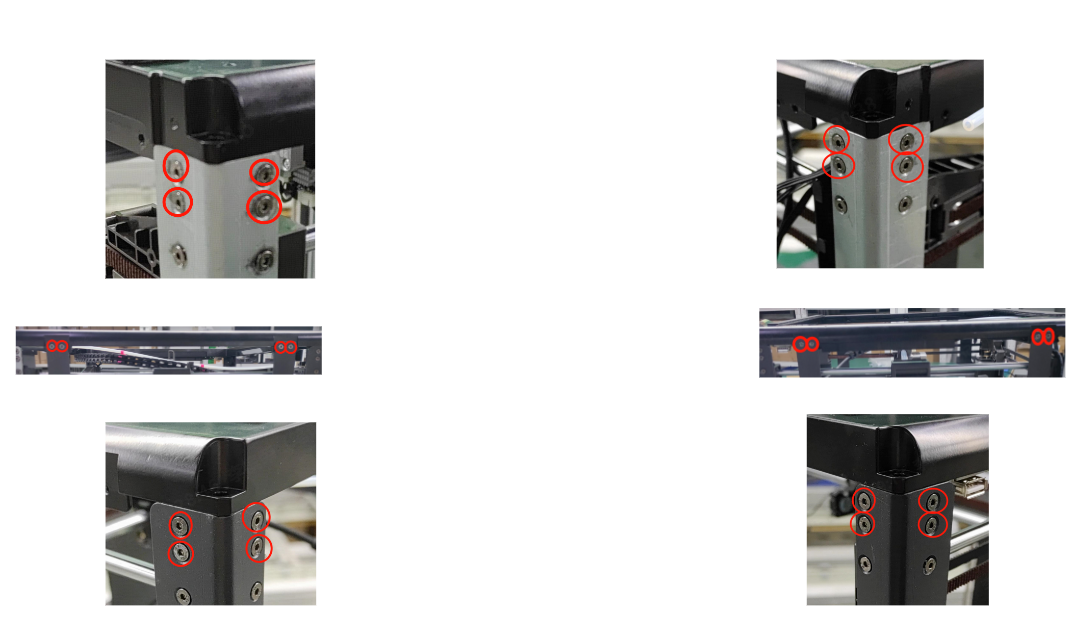
1. Use an S2.0 Allen Key to unscrew the screws that fix the top frame and the fixing plates on both sides.
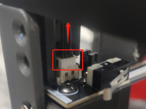
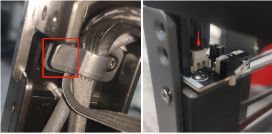
2. Pull the XY limit switch harness upward.
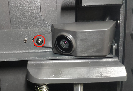
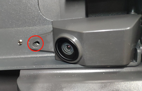
3. Use an S2.0 Allen Key to unscrew the camera housing fixing screws.
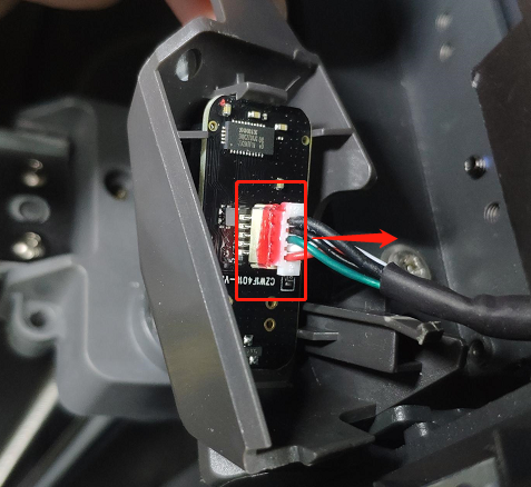
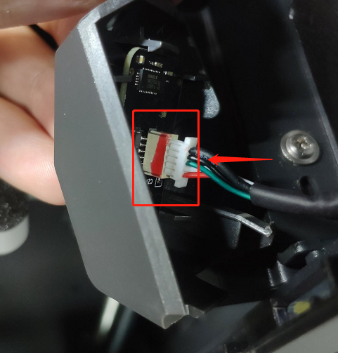
4. Remove the camera harness.
5. Pop open the hub buckle and remove the harness.
Step 5: Disassemble the XY axis assembly
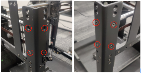
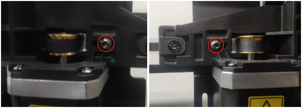
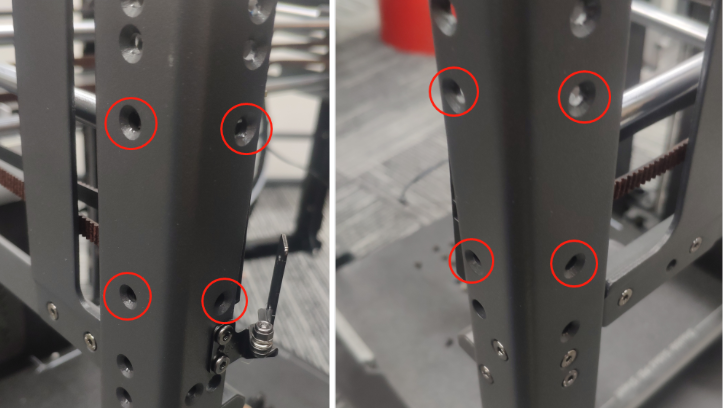
1. Use an S2.0 Allen Key to unscrew the XY axis assembly fixing screws.
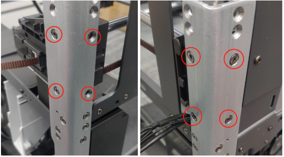
2. Use an S2.0 Allen Key to unscrew the XY axis assembly fixing screws
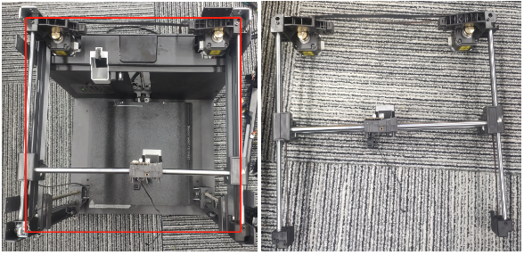
3. Take out the XY axis assembly upwards.
Step 6: Remove the synchronous belt
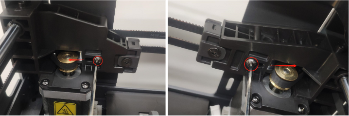
1. Loosen the XY axis tensioners on the left and right sides, and use an S2.5 Allen Key to loosen the tensioner screws.
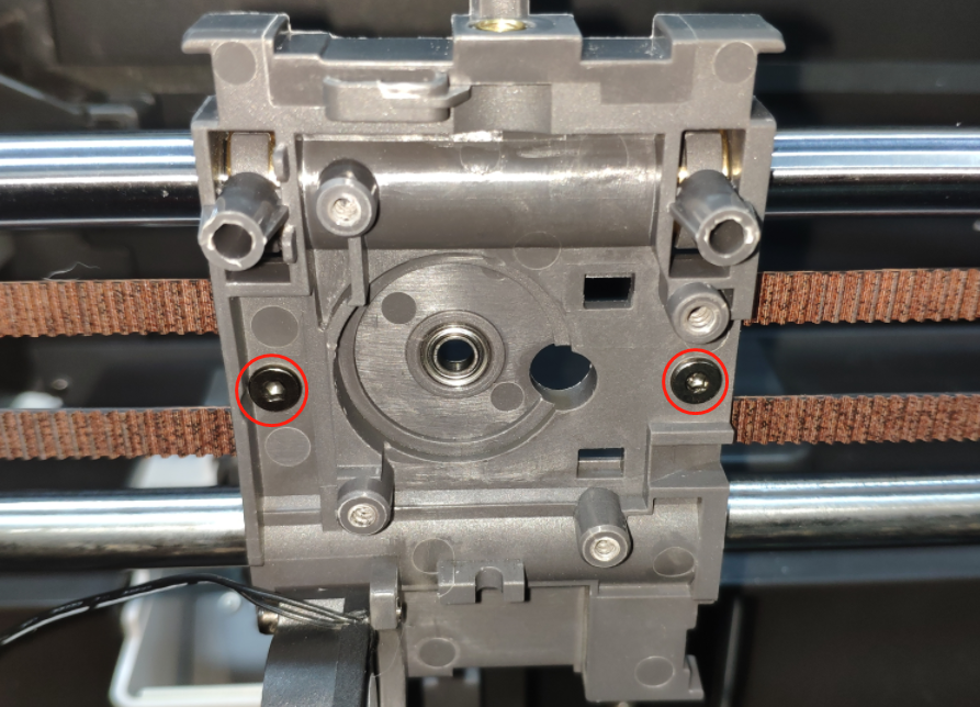
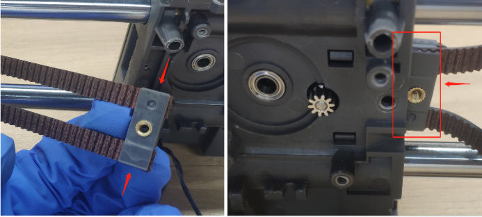
2. Use a 2.0 Allen Key to unscrew the synchronous belt pressure block fixing screws.
3. Installation steps:
Step 1: Install the synchronous belt
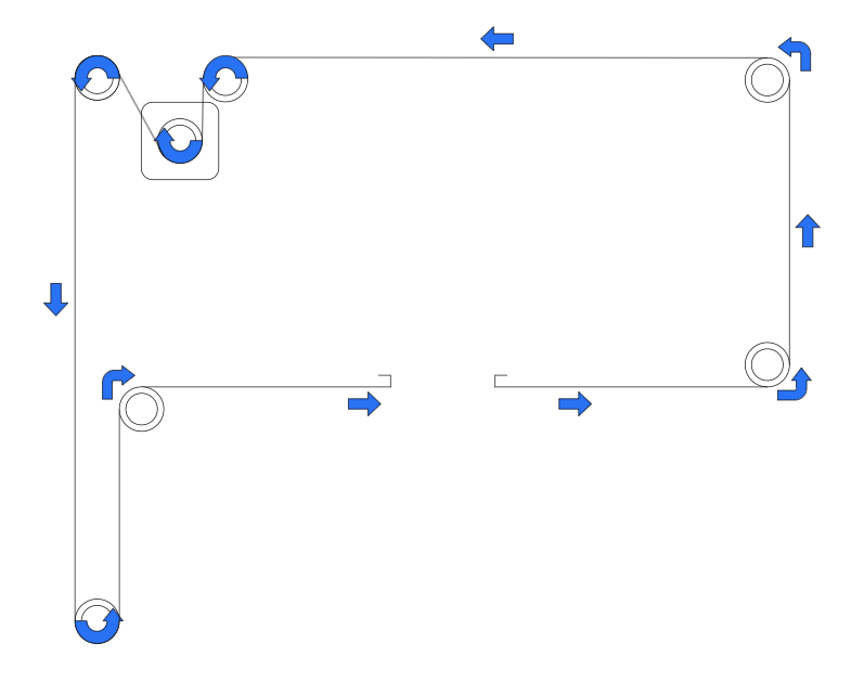
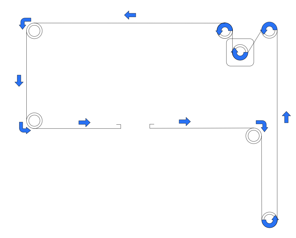
Synchronous belt direction Installation diagram Synchronous belt
2. Press the belt into the synchronous belt pressure block, put the pressed synchronous belt pressure block into the X axis assembly, and use a 2.0 Allen Key to unscrew the synchronous belt pressure block fixing screws.
Step 2: Install the XY axis assembly
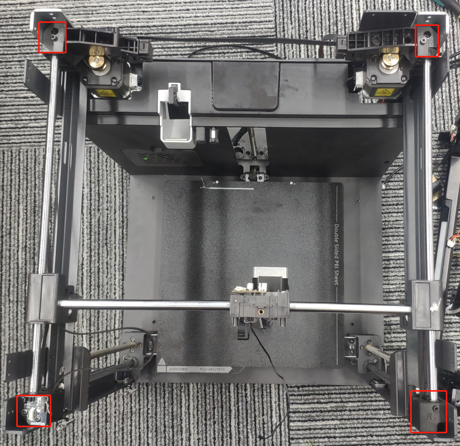
1. After the synchronous belt is inserted, put the four fixing seats of the XY assembly flush into the machine frame, and check whether the synchronous belt is in place.
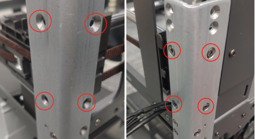
2. Use an S2.0 Allen Key to tighten the countersunk Allen screws of the XY axis assembly.
3. Use an S2.0 Allen Key to tighten the countersunk Allen screws of the XY axis assembly.
Step 3: Install the top frame
1. Install the XY limit switch wires and clip other harnesses into the hub.
2. Use an S2.0 Allen Key to tighten the countersunk Allen screws that fix the top frame and the two side fixing plates.
3. Insert the camera harness into the camera module terminal.
4. Use an S2.0 Allen Key to tighten the screws that fix the camera housing.
5. Tighten the belt tensioner and pull the tensioner outward.
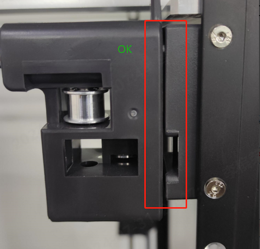
Tip: Slide the X-axis module back and forth twice, move the X-axis to the front of the fixed seat, and check whether the Y-axis slider is close to the fixed seat, as shown in the figure. If it is close to the fixed seat, it is OK, and if there is a large gap between the two, it is NG.
Step 4: Install the extruder assembly
1. Install the extruder module on the X-axis assembly and tighten the extruder module fixing screws with an S2.0 Allen wrench.
2. Insert other harnesses into the slots.
3. Install the material break detection board harness, cutter detection board harness plug, print head harness plug, and print head hot end harness plug.
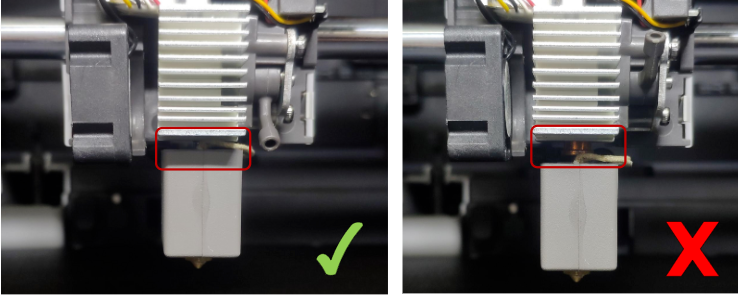
4. Place the quick-release hot end into the heat sink, and pull the buckle down to tighten the hot end.
Check whether the print head is in place.
5. Use an S2.5 Allen Key to unscrew the drag chain fixing screws.